Converting Analog to Digital – How ECM’s Read Sensors
A common question about trucks equipped with the Detroit series 60 engine is why their mechanical boost gauge doesn’t match their electronic boost gauge. Or why does my mechanical boost gauge read 40 psi of boost, but my electronic gauge only reads 32 psi? These are good questions, and the explanation can be used to describe how most of the sensors on your truck work. I frequently mention on our radio programs the sentiment of “it could be a sensor reading wrong.” In this article, I’ll explain what that means and describe how the engine ECM, or any truck computer, ‘reads’ a sensor.
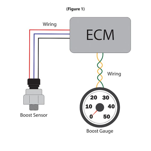
Let’s start by referring to Figure 1. In the picture, there are four components: the boost sensor, the wiring, the ECM, and the boost gauge. The boost sensor is located in the intake manifold on the driver’s side of the engine. This sensor is used to measure the amount of boost pressure that is entering the engine. This sensor is critical for throttle response, power output, fuel mileage, smoke control, EGR control, and more. The boost sensor generates an internal voltage typically via piezoelectricity or by air pressure pushing on a diaphragm. Without going down too much of a rabbit hole, the sensor basically makes more voltage the more pressure that is exerted on it. This continually variable sensor represents real-world data like temperature or pressure. Usually, they operate on a scale of 0-5 volts DC. However, they only have a working range of 0.5V to 4.5VDC. The extra 0.5V at the bottom and top of the range are used for circuit diagnostics. So, if you have a code for circuit low or circuit high, then this tells you that you are in this “no-no” zone of the sensor. The working range of 0.5V to 4.5V represents all the potential boost sensor readings from 0 psi to the max boost sensor reading that is specified by the manufacturer. Pretty cool, right! So, let’s say we have a signal voltage coming from the boost sensor to the ECM that is 4.2V. What does that voltage represent? A calibration machine at the factory samples and quantifies the sensor and let the people coding the ECM know what 4.2V means. They will pump 32 psi into the sensor and record what voltage it registers. The voltage is coded into a table and programmed into the ECM. This code then allows the ECM to measure a voltage from the ECM and determine what boost pressure it is supposed to be based on the preprogrammed look-up table. This process is used for almost all of the sensors. Coolant temperature, intake air temperature, DPF delta pressure, and the list goes on and on.
The ECM uses these look-up table to determine what all the voltages it sees mean. There are a few ways this can go wrong and shows the weakness in the system. Let’s say it is a diaphragm-type sensor. This sensor generates a voltage depending on how much the diaphragm moves. If there is soot in the sensor that blocks it from moving or doesn’t let it move freely, then the reading the ECM gets will be wrong. A freely moving diaphragm would read 30 psi, but a stuck diaphragm may only be able to read 15 psi. Since the ECM relies solely on the voltage reading, it has to be accurate for the ECM to make correct decisions. Stuck-in-range sensors give the ECM incorrect readings which can affect fuel mileage, EGR flow, DPF performance, engine response, misfires, etc. It is important to routinely clean sensors or change them on a schedule. They don’t last forever!
The answers to the questions in the introduction paragraph are this: why their mechanical boost gauge doesn’t match their electronic boost gauge? It may be because of a stuck-in-range sensor or because the programming for that sensor is incorrect. Someone may have put DDEC 3 programming into a DDEC 4 ECM. Those ECMs look similar but interpret boost sensor voltages different. The other question: why does my mechanical boost gauge read 40 psi of boost, but my electronic gauge only reads 32 psi? This is most likely because the J1708 has a limitation that it can only display a maximum of 32 psi REGARDLESS of what the ECM sees.
Broken or malfunctioning sensors is something that every truck owner deals with. The process of converting a signal voltage to a number that the ECM can read is a sensitive process without any redundancy. There are no ‘backup’ sensors that the ECM can rely on if one goes bad. As technology progresses, sensor issues can be reduced with increased redundancy and signal verification. Until then, the best thing you can do is to set yourself up with a routine schedule to replace sensors before they go bad.
Written by: Leroy Pershing, Pittsburgh Power Inc., 3600 S. Noah Drive, Saxonburg, PA, 16056 Phone (724) 360-4080 Email: [email protected] Website: www.PittsburghPower.com